Let's play Pick One From Column A, One From Column B & One From Column C.
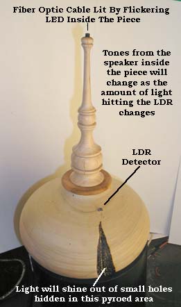
What I'm after is a sensor a Participant can interact with, something for it to trigger and something going on while all that is happening. So let's pick the LDR (Light Detecting Resistor in a "Voltage Bridge") as the DETECTROR, a small speaker for the TRIGGERED ACTION - and an LED to be flickering all the time ATTRACTOR to draw a viewer close enough to begin interacting with a piece.
Here's the What and What Connects To What.
Here's the "sketch" ("C" program) that runs this stuff. You can select its text and copy it into a blank Arduino "sketch". After you've breadboarded the set up and played with the "sketch", tweeking things to see what happens, we'll move on to a Real World Application.
// LDR_Piezo_Flicker
//
// This example uses an LDR (Light Detecting Resistor) in a Voltage Bridge Circuit
// to detect changes in the amount of light falling on the LDR. As the amount of
// light goes up, the LDR's resistance goes down. The Arduino receives the change
// and based on the voltage Analog Pin #1 "sees", converts that input into a voltage
// value to send to the Speaker, changing its tone.
// while all that is being done, an LED is flickering randomly like a candle does
/*
* Parts List:
*
* Arduino Duemilanove nicro controller (means 2009 in English)
* USB cable to connect your computer to the Arduino's USB port
* 10K ohm 1/4 watt Resistor
* 0-20K ohm Light Detecting Resistor (LED)
* Piezo electric "buzzer" 3-16V DC (Radio Shack Part No. 273-074)
* 30 rows of pins Breadboard
* LED (Color of your choice)
* 220 ohm resistor
* jumper wires
*
* What Connects To What aka Schematic DIAGRAM
*
** GND<-----------------------------------.-
*...............................................|
*............................................ (R) 10K ohms
*.............Analog .....................|
* )<------------------------------------------: [ VOLTAGE DIVIDER ]
*.......... Pin 1 ..........................|
* .........(0-1023)...................... |
* .........................................(LDR) 0-20K ohms
*............................................. |
* .............................................|
* +5V .---------------------------------->.
*
* GND<-------------.
*....................... |
* ...................--------.
*................. /......... \
*................ | Piezo |
*................ | Buzzer |
* ................\........... /
*................. +--------/.
* .......PWM .......|
* )--------------------->. Positive leg of Piezo buzzer
* ..Digital Pin 8
*... (0-254)
*
* Digital Pin 6
*)----------------|220 ohm resistor|-----.
*..................................................|
*..................................................|
*...............................................--+--.
*.............................................| LED | Note: LONG lead
*.............................................:__.__: of LED is POSITIVE
|*.................................................|
*)----------------|220 ohm resistor|-----.
*..................................................|
*GND -----------------------------------------.
*/
int photosensorPin = 1; // center leg of LDR & R Voltage Divider is attached to Analog Pin 1
int piezoPin = 8; // the + leg of the piezo buzzer or speaker is attached to Digital Pin 8
int LDRval = 0; // Zeros out the variable that will hold the LDR & R voltage divider output
int LDRsensorVal = 0; // identifies the variable "LDRsensorVal" as an integer variable
int LDRsensorLim = 900; // limiter on how much of Voltage Divider's value goes to piezo/speaker
int LDRcyclesAdj = 75; // adjust LDR cycles /tone. 250,10,2.5=SciFi 75,10,2.0=Nice tones
int LDRdelayAdj = 10; // adjust LDRdelay between tones. Recommended value +/-10
int LDRsensorDivisor = 2.0; // divisor when trimming sensor's raw output value down for buzzer range
// Value must be in the 1.0 to 4.0 range, with 2.0 recommended
int LED = 6; // LED that will be flickered connected to Digital Pin 6
int jFlick = 0; // will be a random number between 0 & 255 for LED brightness
int kFlick = 0; // will be random number between 0 & 90 for how long brightness is ON
// BEGIN setting up initial conditions
void setup()
{
pinMode(piezoPin, OUTPUT); // sets Digital Pin 3 (PWM) as an OUTPUT pin. Will be the input to the piezo buzzer
pinMode(photosensorPin, INPUT); // sets Analog Pin 1 to an INTPUT pin. Pin 1 will RECEIVE values FROM voltage divider
// pinMode(LED, OUTPUT); // sets digital pin 6 that LED is connected to as an output pin feeding power to LED
}
void loop()
{ // ----------------------------->the top of the "outer loop" below
digitalWrite(piezoPin, LOW); // sets the piezPin OFF/LOW
LDRval = analogRead(photosensorPin); // reads Pin 0's analog value from photosensor
LDRsensorVal = LDRval; // LDR is the photosensor's output value that's halved to get it in the speaker's range
if(LDRsensorVal > LDRsensorLim)
{
LDRval=0;
}
LDRval = LDRval/LDRsensorDivisor; // halves the photosensor's value Pin 0 assigned it
for( int i=255; i > LDRcyclesAdj; i-- )
{
// play TONE
digitalWrite(piezoPin, HIGH);
delayMicroseconds(LDRval + LDRdelayAdj);
digitalWrite(piezoPin, LOW);
delayMicroseconds(LDRval + LDRdelayAdj);
// Flicker LED
jFlick=random(0,255); // generates a random number between 0 & 255 for brightenss
kFlick=random(0,90); // generates a random number between 0 & 90 for brightness duration
analogWrite(LED, jFlick); // set the LED brightness
// delay(kFlick); // leave it on for this amount of time
analogWrite(LED, 1); // set the LED brightness
// delay (10);
}
} // <--------------------------- the bottom of the outer loop