Beyond Movement - Interactive Pieces
What I hope to do with what follows is to show you some of what can be done to add micro computer controlled interactivity to a piece and maybe make it a little easier for you, should you want to try some of these ideas. If you have any questions about what follows or comments or suggestion - please e-mail me charlieb@accesscom.com
Turning is a very Hands On dynamic process. BUT the result is usually - LOOK BUT DON'T TOUCH. STATIC. This seems bit paradoxical.
So - I've been exploring ways to add ACTUAL movement to my pieces - using springs wires, springs, swivel joint "pendulums", small wind up toy mechanisms and little battery powered motors with gears and drive shafts.
Then I "discovered" a HexBug's CRAB - an autonomous micro robot - that can sense and react to light and sound / vibration by scurring away - crablike. Movemtent without actual contact. Hmmmm . . . Clap your hands - it moves. Shine a light on it - it moves. Stomp your foot - it moves. Touch it - it moves. So I turned a sugar bowl, with lid - and hid a CRAB under it. Lift the lid - the bowl scurries away! Turned upside down, the CRAB's legs wave around in the air. Extend the legs with some spring wire, stick some "gummy bear" type creepy, wiggley fishing lures on the ends of the wires - and then put that inside a "ginger jar" piece. Lift the top off and you're faced with a mass of wiggling and waving around "things" . But that's ALL the CRAB did - move its legs - or not - when triggered by sound/movement or light - all controlled by a tiny hardwired micro chip "brain".
What I needed was a bigger little brain - that wasn't hard wired - but - programmable.
Peter Rand, a turner also interested in "kinetic" pieces, turned me on to "stamp controllers" - small, battery powered micro computers with places to connect "sensors" and "action" components. And - these things are programmable. Hmmmmm . . .
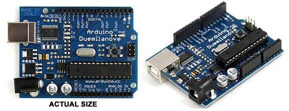
Months later, at a Makers Faire, I came acrossed folks selling Arduinos and parts and accessories for them. It's basically a 16Mhz micro processor with 32K of internal memory,a USB port for powering it AND downloading software to it, a power connector port for a transformer or wired up 9V battery power source - along with pins to which components can be plugged in.
There are a TON of relatively inexpensive components available - sensors and action components. There are pressure pads, sound detectors, tilt detectors, light detectors, infra red motion sensors, accellerometers, magnetic field detectors - a host of other sensors/detectors. And on the "actions" side - LEDs, RGB LEDs, small speakers and buzzers, cell phone vibrators, stepper motors, servos, LCDs . . .
The programming is done using "C" a fairly primitive but useable programming languge that produces pretty compact code - memory being limited to 32K. There are a lot of tutorials on how to program the Arduinos and several Arduino Users Forums to help newbies to Arduino get up the learning curve more easily.
OK - so what can you DO with one of these "stamp controller" things?
Well here's my first idea:
A bit of time on several Arduino sites going through tutorials,downloading example "sketches" (sounds less intimidating than "computer programs) and some sticking parts and jumper wires in the "breadboard" and it was time to play with some sensors and "action" parts. Soon I had understood some of the basic ideas of what did what - and how. It was time to put some things together in a Prototype Piece.
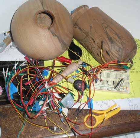
Going from Idea to Prototype required a few tools - soldering iron, wire strippers, wire cutters - some solder - wires, shrink tubing, crimp on then solder pins and plugs and some parts - Light Detecting Resistors (LDRs), LEDs, RGB LEDs, a piezo electric buzzer, a small 8 ohm speaker, a photo electric infra red sensor (PIR), a small servo and a littlecell phone vibrator motor - along with a "breadboard" stuff could be plugged into - parts and jumper wires from the breadboard to the Arduino. For the "piece" - a short piece of 4" diameter ABS pipe I could drill holes in for light to get IN and stuff to get OUT. My desk became a Mad Scientist's Workbench. This slips into that and that plugs into this over here, download the "sketch" and . . . NOTHING HAPPENS! Oh - THIS wire should be plugged in HERE. Try again. IT WORKS! Look everybody - I've turned on an LED! (Big deal - you turned on a light. Big phreakin' deal.)

Another couple of days of Pluggin' & Playin' and I could get The Thing to sing or howl like A CAT as the shadow of my hand passed over a sensor. I could get the inside of the "piece" to glow - though the different colors of the spectrum. I could get a sensor to tell if I'd moved in its field of view. If I got close enough and stayed still for 1 or 20 seconds, it could even detect when I blinked my eyes - or stuck out my tongue.
Hmmmmm. THIS is getting INTERESTING.
Quickly realized that it was time to start going at things more methodically if I wanted to avoid a bit of work modifiying "sketches" I'd downloaded.
Turns out some kind soul created a graphics program that was just what I needed - FRITZ. A Mac, Windows and Linux version is availale for free download - the link to get it will be provided later. A menu of graphics of components, a way of adding "notes" and a method of doing color coded wiring - and I've got a diagram of the Arduino, Breadboard, Components I'll likely be using - and Ta-Da - a Wring Diagram - that shows which wire connects to what. Perfect for Breadboarding.
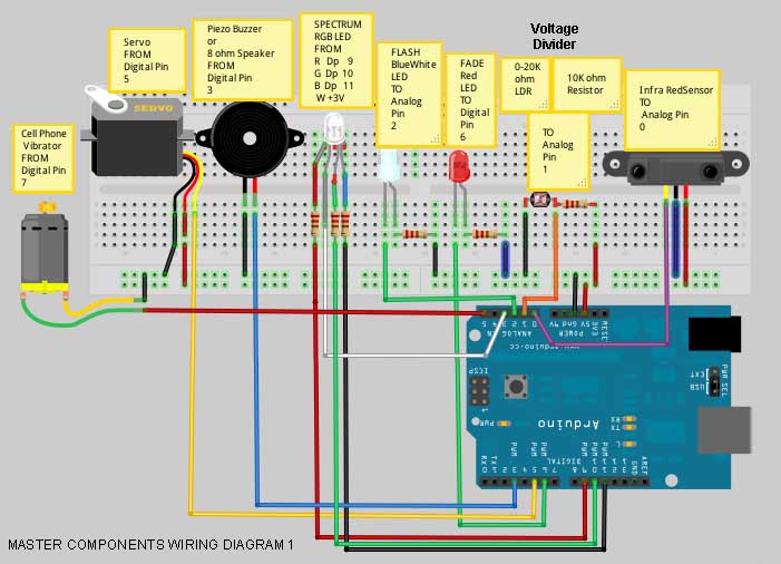
Now when you're prototyping on a breadboard, you can see ALL the wires and be able to see which wire is ACTUALLY (as opposed to INTENDED TO) connected to what. It's pretty easy to find out what's connected the wrong way - and fix things. BUT - when one set of wire ends are INSIDE a prototype piece and you can only see the wire ends that must go to the Arduino - well things start getting messy - unless you've got a lot of little wire - in a half dozen or so colors.
NEED a way to bring Order to this Chaos.
Wire Harnesses - with Plugs - maybe phone jacks, plugs and 4 and 6 strand phone cords. Another FRITZ diagram to keep track of what connects to what with which jack and plug - and the component Label also being the "sketch" name that will use them. This way each component and it's "sketch" can be tested BEFORE putting several of them together in a piece - then use one "sketch" as the main program and include others as "functions" (aka Subroutines). This Modular Approach will make doing a variety of pieces using any combination of these parts and "sketches" just a little Some Assembly Required operation - rather than another go at Re-Inventing The Wheel. Shouild also make things easier for YOU, should you want to play with this idea and stuff.
Making these Building Blocks requires some stripping and soldering of little wires and some shrink tubing - but once I work out easy ways to make them up - and put together their program "functions" - putting them together and making them do things should be pretty straight foreward. Will post the HOW TOs and "sketches", along with instructions for use as I go along. My hope is that if I can make it easy enough for the next person - they'll share what they did with it.