In the first micro controller controlled example, we were playing with adding internal lighting to a piece - and getting that light to flicker - like a candle. This next example uses an internal light source as well - but rather than have it stream out of cracks and splits in the piece - we'll take that light out - to specific locations on the OUTSIDE of the piece . The source of the light won't be seen - because it's hidden INSIDE the piece.
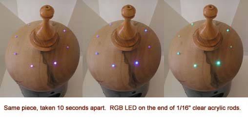
Just for fun - and because we CAN - let's also have the color of the light change - to any color in the visible spectrum - actually scrolling through the visible spectrum. You can do that with what's called an RGB LED, which has a Red, Green and Blue LED inside one clear plastic lens. Thanks to the micro controller - we can turn on and combination of the three LEDs AND independently change each one's brightness.
This set of photos of the piece will give you an idea of how this idea might work - and show you just one of the ways to get light from INSIDE to OUTSIDE. The little points of light appear just a surface decoration - when the RGB LED is off.
Just for fun - let's add a sensor to the idea - that can detect when the amount of light falling on it changes - and tells the computer that it has.
The detector is a little Light Detecting Redistor or LDR that you can get at most any Radio Shack or on line - for less than fity cents. What it does is change its resistance to current flowing through it based on the amount of light stricking it. No light - it's like and open circuit - no current flows. Full sunlight falling on it - it acts like a normal conductive wire - allowing curent to flow through it. Less light - less current - more light - more current. With a twenty cent resistor - which you can also get at Radio Shack - you can make what is called a Voltage Divider Circuit.
Here's the wiring illustration
OK - is a bit more complicated than the Flickering Candle idea. The RGB LED needs four wires instead of two, one for Red, one for Green and one for Blue as well as one to complete the electrical connection - and three of those wires each needs a resistor - to keep from frying the RGB LED. The Voltage Divider needs three wires - a PLUS, a MINUS and a SIGNAL wire.
The R, G & B wires connect to pins on the micro controller, pins 9, 10 & 11, and the software will tell the computer these pins are for OUTPUT - from the micro controller to each of the LED's three colors. The center wire - the SIGNAL wire - of the Voltage Divider circuit is attached to pin 4 on the micro controller. The software tells the micro computer to look for signals coming from the Signal wire of the Voltage Divider - so it's configured as an INPUT pin TO the micro controller
And here's the "sketch" (program) that will detect your shadow falling on the piece and then light up the little "beads" on the piece, changing their colors through the spectrum - as long as the "sensor" is shaded. It's a bit longer because your changing how much light each of the three LEDS, Red, Green and Blue, are to put out.
Again, note that the "//" and anything after "//" are comments - ignored by the compiler that translates the sketch into 0s and 1s the micro controller understands.
/* MiddleSisterFINAL
* RGB_LED_Fade9_10_11 when LDR Voltage Bridge center leg
* drops below a "Trigger" value, YOU specify, due to a
* shadow blocking the amount of light getting to the LDR * Code for cross-fading a tri-color RGB LED,
* using PWM
* The program cross-fades slowly from red to green, green to blue, and blue to red
* The debugging code assumes Arduino 0004, as it uses the new Serial.begin()-style functions
* originally "dimmingLEDs" by Clay Shirky <clay.shirky@nyu.edu>
*
* R G B L E D
* NEGATIVE (-) "center leg"
*
* RGB_LED_Fade9_10_11 when LDR Voltage Bridge center leg
* dops below a "Trigger" value, YOU specify, due to a
* shadow blocking the amount of light getting to the LDR * Code for cross-fading a tri-color
* RGB LED, using PWM
* The program cross-fades slowly from red to green, green to blue, and blue to red
* The debugging code assumes Arduino 0004, as it uses the new Serial.begin()-style functions
* originally "dimmingLEDs" by Clay Shirky <clay.shirky@nyu.edu> *
//
// Put your Variables up here - BEFORE "void setup()"
//
// Components' input and output pin number identification
//
int LDRpin = 4; // Center Leg of LDR voltage bridge
int redPin = 9; // Red LED, connected to digital pin 9
int greenPin = 10; // Green LED, connected to digital pin 10
int bluePin = 11; // Blue LED, connected to digital pin 11
//
// Program variables set as integer (number) type
//
int redLEDValue = 255; // Variables to store the values to send to the pins
int greenLEDValue = 1; // Initial values are Red full, Green and Blue off
int blueLEDValue = 1; // These values get passed to the analogWrite() function.
int i = 0; // Loop counter
//
int Trigger = 850; // This is the LDR "trigger" value
// should be between 0 and 1023
// 800 is about the amount of light from
// a desk lamp shinging on the LDR from 2 feet.
// 600-650 is about ambient light level in
// window lit room
// tweek "Trigger" value to tune for your lighint
// conditions
//
int LDRval = 0; // LDRval is the reading of the center leg of
// the LDR voltage bridge circuit
void setup()
{
pinMode(redPin, OUTPUT); // sets the pins as output
pinMode(greenPin, OUTPUT);
pinMode(bluePin, OUTPUT);
Serial.begin(9600); // comment this out after debugging
}
void loop ()
{
Serial.print(" Read Sensor. val = "); // comment out after debugging
int LDRval = analogRead(4);
Serial.print(LDRval); // comment out after debugging
if(LDRval <= Trigger)
{
//
// Put the code for the EVENT you want "triggered" here
// ================
{
i += 2; // Increment counter
if (i < 255) // First phase of fades
{
redLEDValue -= 1; // Red down
greenLEDValue += 1; // Green up
blueLEDValue = 1; // Blue low
}
else if (i < 509) // Second phase of fades
{
redLEDValue = 1; // Red low
greenLEDValue -= 1; // Green down
blueLEDValue += 1; // Blue up
}
else if (i < 763) // Third phase of fades
{
redLEDValue += 1; // Red up
greenLEDValue = 1; // Green low
blueLEDValue -= 1; // Blue down
}
else // Re-set the counter, and start the fades again
{
i = 1;
}
// analogWrite() expects 2 parameters, the object/pin and a value between 0 (off) and 255 (full on)
analogWrite(redPin, redLEDValue); // Write current values to LED pins
analogWrite(greenPin, greenLEDValue);
analogWrite(bluePin, blueLEDValue);
// comment out all the following "Serial.print" lines after debugging
Serial.print("redLEDValue = "); // comment out after debugging
Serial.print(redLEDValue); // comment out after debugging
Serial.print(" greenLEDValue = "); // comment out after debugging
Serial.print(greenLEDValue); // comment out after debugging
Serial.print(" blueLEDValue = "); // comment out after debugging
Serial.println(blueLEDValue); // comment out after debugging
delay(10); // Pause for xx milliseconds before resuming the loop
}
// ================================================
// ***********************************************
// end of primary loop beginning of secondary loop
// ***********************************************
// ================================================
}
Serial.println(" Waiting for Trigger Event "); // comment out after debugging
analogWrite(redPin, 0); // Turn RGB LEDs OFF
analogWrite(greenPin, 0);
analogWrite(bluePin, 0);
delay(10);
}
See the YouTube video of this piece in action by CLICKING HERE