Here's a quick tour of this micro controller / micro computer / stamp controller.
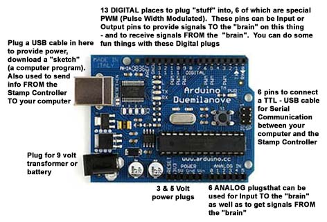
And here are just SOME of the things you can connect to the Micro Controller - to sense things - AND - to react to things.
Sensors can detect changes in light - in the visible spectrum as well as in the infra red range - changes in sound levels - both in the audible range as well as in the ultra sonic and sub sonic range, changes in pressure and temperature - as well as movement. And once a change is detected - the "brain" can trigger "reactions" - light, sound, movement or any combination.
Here's an example of using a few of the above components. There's a "sensor " that detects changes in the amount of light falling on it (a Light Detecting Resistor - aka LDR) - a small speaker that the "brain" can "tell" to make a sound or sounds when the LDR tells it something has changed - and by how much - AND - a light that flashes, flickers or fades up and down - to attract attention. There's a free Drag & Drop graphic program that created this illustration - and it makes it fairly easy to keep track of What Connects To What. A link to where you can get that software for free will be provided in the LINKS of this "micro controller introduction".
Here's the "sketch" (computer program) that will cause the LED to FLICKER and the LDR to monitor the amount of light falling on it - telling the "brain" how much - and then have the "brain" tell the little piezo electric buzzer or a small speaker to generate a sound - that changes with the light level the LDR is "seeing". What follows is the "short version" of the "sketch" with minimal comments. I didn't WRITE the guts of this "sketch" but downloaded them from one of the many internet sites that have plenty of example tutorials, some including videos. You can cut and paste the following "sketch" or download a heavily commented version, with an ASCII diagram of what connects to what by clicking HERE,
// This “sketch” takes info about how much light is falling on a light detector resistors
// and uses that info to change the sounds a speaker makes
int photosensorPin = 1; // center leg of LDR & R Voltage Divider is attached to Analog Pin 1
int piezoPin = 8; // the + leg of the piezo buzzer or speaker is attached to Digital Pin
int LDRval = 0; // Zeros out the variable that will hold the LDR & R voltage divider output
int LDRsensorVal = 0; // identifies the variable "LDRsensorVal" as an integer variable
int LDRsensorLim = 900; // limiter on how much of Voltage Divider's value goes to piezo/speaker
int LDRcyclesAdj = 75; // adjust LDR cycles /tone. 250,10,2.5=SciFi 75,10,2.0=Nice tones
int LDRdelayAdj = 10; // adjust LDRdelay between tones. Recommended value +/-10
int LDRsensorDivisor = 2.0; // divisor when trimming sensor's raw output value down for buzzer range
// Value must be in the 1.0 to 4.0 range, with 2.0 recommended
// BEGIN setting up initial conditions
void setup()
{
pinMode(piezoPin, OUTPUT); // sets Digital Pin 3 (PWM) as an OUTPUT pin. Will be the input to the piezo buzzer
pinMode(photosensorPin, INPUT); // sets Analog Pin 1 to an INTPUT pin. Pin 1 will RECEIVE values FROM voltage divider
}
// BEGIN running the part of the “sketch” that reads the LDR and tells the speaker what to do
void loop()
{ // ----------------------------->the top of the "outer loop" below
digitalWrite(piezoPin, LOW); // sets the piezPin OFF/LOW
LDRval = analogRead(photosensorPin); // reads Pin 0's analog value from photosensor
LDRsensorVal = LDRval; // LDR is the photosensor's output value that's halved to get it in the speaker's range
if(LDRsensorVal > LDRsensorLim)
{
LDRval=0;
}
LDRval = LDRval/LDRsensorDivisor; // halves the photosensor's value Pin 0 assigned it
for( int i=255; i > LDRcyclesAdj; i-- )
{
// play it for 50 cycles
digitalWrite(piezoPin, HIGH);
delayMicroseconds(LDRval + LDRdelayAdj);
digitalWrite(piezoPin, LOW);
delayMicroseconds(LDRval + LDRdelayAdj);
}
} // <--------------------------- the bottom of the outer loop
To see a YouTube video - with sound - of a woodturning that uses this set up - click HERE
Let's look at those components and get into what they are and what they can do ----------->